
Introduction
I remember walking into a small PCB shop where the solder smoke hit you like a warm wind off the plains — and the techs just shrugged. In that room, fume extraction for electronics and industrial applications was treated like an afterthought, even though bench tests and field reports often show VOC spikes during reflow cycles and visible flux residue on nearby surfaces. So, what gives — why do experienced teams still wrestle with simple air quality problems that cost health, yield, and peace of mind?
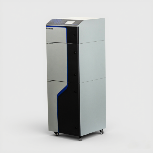
Here’s the scene: a line full of reflow ovens, a handful of local extractors, and a manager who says production can’t stop for “another upgrade.” The data whisper back: higher sick days, slower line speeds, occasional product rejects — and yet the fixes that promise relief are ignored. (I’ll be frank — I’ve seen this a dozen times.) Let’s walk through what went wrong, and then look at hands-on, clear ideas that actually work. Next up, I’ll break down the core flaws in the usual fixes so we know what to avoid.
Traditional Fixes: Where They Fall Short
When I look at reflow soldering setups, I often see the same mistakes repeated: underpowered hoods, filters mis-specified for VOCs, and systems designed around airflow numbers rather than capture efficiency. Traditional extraction assumes you can just bolt on a fume extractor and call it done. But capture hood geometry, nozzle placement, and the chemistry of the solder paste and flux matter a lot. HEPA filters grab particulates, sure, but they do nothing for volatile organic compounds. So lines keep smelling like flux — and workers keep coughing. Look, it’s simpler than you think: match the control method to the contaminant — particulate controls for dust, activated carbon or catalytic stages for VOCs — instead of treating them interchangeably.
Why do old systems fail?
Most failures come down to three avoidable habits. One: design by numbers — people pick a fan rated for X CFM and assume capture follows. Two: maintenance neglect — clogged pre-filters and ignored carbon beds cut capture time in half. Three: recirculation without treatment — pulling air back into the room without removing solvents just spreads the problem. I’ll admit, I’ve been guilty of underestimating placement myself early on; you learn fast when sensors tell you the capture efficiency is 30% and not the 90% you hoped for — funny how that works, right?
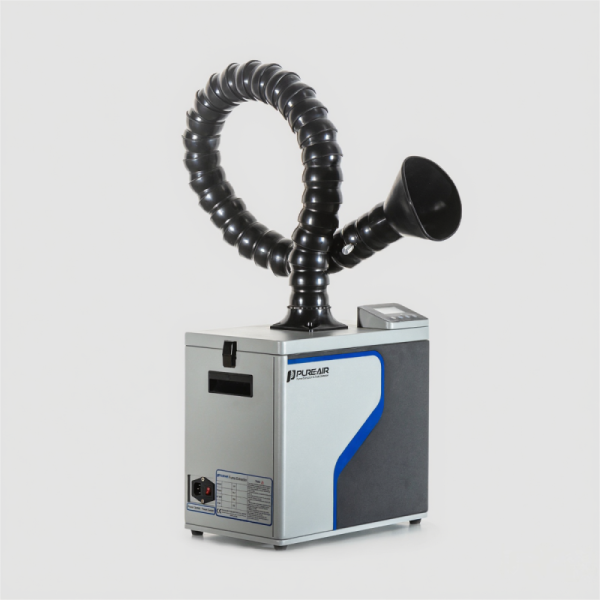
Looking Ahead: Principles for Smarter Fume Control
Building on those hard lessons, I prefer a forward-looking, principle-driven approach rather than quick fixes. For modern reflow soldering lines, think zoning, real-time sensing, and matched abatement stages. Use local capture hoods tuned to the reflow profile, add activated carbon or catalytic VOC treatment downstream of particulate stages, and deploy sensors that feed edge computing nodes for automated fan and damper control. That combination keeps contaminants from ever spreading across the line, and it keeps energy use sensible — yes, you can have both safety and efficiency.
What’s Next?
Practically speaking, I recommend three evaluation metrics when you compare systems: capture efficiency at the source (measured, not assumed), VOC abatement percentage for the specific flux chemistry you use, and system maintainability (filter access, replacement costs, and sensor calibration intervals). Measure those, and you’ll stop buying toys and start buying solutions. — and yes, budget matters; but poor choices cost more over time. For teams ready to upgrade, these metrics help focus spending where it counts: worker health, process yield, and predictable uptime. For guidance and components that line up with these principles, I often point colleagues to well-designed vendors like PURE-AIR.